Frequently Asked Questions
In our 30+ years helping customers develop products, we have collected and responded to many common questions. If you’re stuck, or not sure what to do next, give our Frequently Asked Questions (FAQ) a look. We may have already addressed your problem. Need something else? Contact our Technical Support team.
SLCD Controllers
- All SLCD
- Application Consultants
- Communication
- Connectivity
- Development
- Environmental/Regulatory
- Features
- Fonts
- Getting Started
- LabView
- Mounting
- Performance
- Power
- Price/Availability
- Programming with Qt Creator
- Programming with Qt/QML/C/C++
- Screen
- Storage
- Troubleshooting
The RESET input is driven high (to 3.3v) by the on-board reset controller. You can drive it low through an open-collector circuit to reset the board, but you should not drive it high. If you need to, use the voltage present on J1 pin 1.
The typical room temperature current is as follows, measured at 5V DC input:
- CASE 1 – Full bright “xbb 255”, blank screen: 238mA
- CASE 2 – Full bright “xbb 255”, checkerboard screen: 243mA (the checkerboard pattern alternating white and black pixels is worst-case panel power)
These are typical numbers. We quote the absolute worst case (400mA) on the datasheet; it is improbable that all parts of any particular module will be the worst case.
See the inrush power on applying power to the module in the image below.
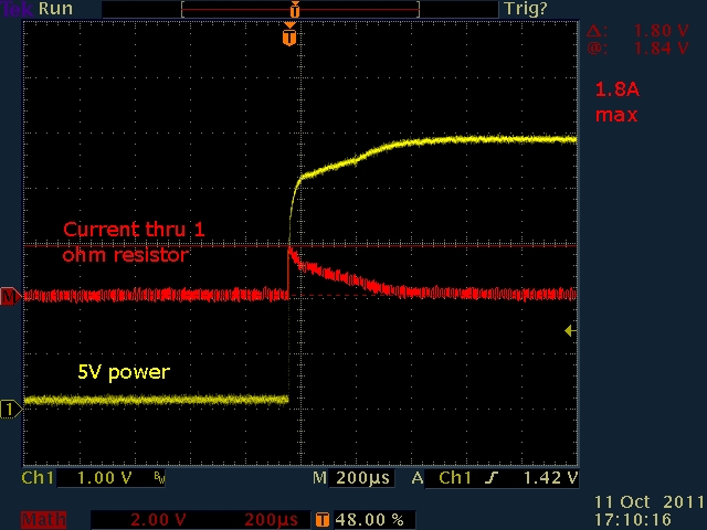
This surge charges the tantalum capacitors on the board. The module contains a supervisor reset chip MCP809T with a minimum delay of 150mS from power. So as long as the caps are charged in 100mS, all will be well. You could easily limit the inrush current to 400mA and be okay.
One option is to define a macro the application can use when needed. A macro can turn the display off with the “v off” command. First, define a particular hotspot over the entire screen, then assign this hotspot to another macro. When the user touches any location on the touch screen, the assigned macro is run. The ‘wake-up’ macro could remove the hotspot and turn the display back on with the “v on” command. A screen touch can notify the application with either a standard “x” notification from the SLCD or a custom message from the ‘wake-up’ macro. See the example macros in the file PowerSaveExampleMacros.txt.
The firmware in our SLCD5/SLCD5+ display modules does not support SDHC cards (those over 2 GB capacity). This is because the low-level SD card protocol changed, so even if you partition the SDHC card and create a FAT16 file system, the underlying protocol is incompatible. You will need to use a standard SD card with a capacity of 2 GB or less.
The 5.7″ QVGA (320×240) is an older standard than the 4.3″ display, and that’s why the 5.7″ has a lower resolution. The lower the resolution, the higher the brightness, so the 5.7″ does have one redeeming feature. We favor “standard” sizes and resolutions as much as possible for long-life availability. There are no standard bodies for small TFT displays, only form factors and resolutions adopted by multiple vendors.
You have several options for higher resolution, and these are all powered by our SLCD5 controller. These options are very similar in resolution (dots per inch (dpi) or pixel pitch).
Reference 4.3″ dot pitch 0.198mm = 128dpi
Options:
- 5.7″ VGA (640×480) dot pitch 0.180mm = 141dpi (tighter than the 4.3″)
- 6.4″ VGA (640×480) dot pitch 0.204mm = 124dpi
- 7″ WVGA (800×480) dot pitch 0.190mm = 134dpi
All of the above are available from multiple panel vendors.
Under “Touchscreen Display Modules” choose the product you are using. Under the “Downloads” tab, select Portrait Firmware to download the .UPG file. Use the BMPload program to change the firmware.
Note: SLCD5/SLCD5+ products display landscape orientation only and cannot do portrait orientation.
The Progressive format of JPEG files can use a large amount of RAM, which, with large images, can easily exceed the RAM available in the display module. The fix is to not use the Progressive format and to stick with the Baseline format. Find more details at http://kb.tourwriter.com/baseline-jpeg-vs-progressive-jpeg.
There is a command to tell the controller to execute a macro when there has been no activity on the serial port to the host. The command “*comwdt” can be used to enable the detection of communication timeout events and execute a macro in response. Please refer to Communications Watchdog Timer Documentation for complete details.
All SLCD controllers have a reset circuit triggered when the voltage supplied to the board drops below a particular threshold. Sometimes called brown-out protection, this trigger ensures the controller’s processor does not incorrectly execute and possibly change its internal programming when it loses power. This reset happens when the input voltage to the controller sags (dips down below 10% of nominal).
The display backlight draws a lot of power, and when it turns on, the controller input voltage can sag and cause the controller to reset and turn off the backlight. This can make it look like the display is flashing since it turns on the backlight and then resets and keeps doing this as long as power is applied. The solution is to shorten the cable between the power source and the controller or use larger cable wires. Long thin power cables have inductance which can cause voltage sags when there is a change in current. To see the problem, put an oscilloscope on the controller power input and set the trigger at 10% less than the nominal input voltage.
Natural images (pictures) display quite well using 16-bit color. However, some computer-generated artwork images contain continuously varying color gradients that look banded when converted to 16-bit color. To resolve this, use error diffusion (dithering) to smooth out the banding. Look in the GIMP documentation or glossary for information on dithering support.
Make sure Windows isn’t renaming the file for you. Some web browsers insist on renaming the file .STEP to .txt. To work around this, you can either do a right-click on the link, select Save as…, or rename the file to a .STEP file.
Question:
I have programmed the baud rate at 23
,
*PONMAC 0
4
,
*PONMAC 0
,
*PONMAC 0
in the power-on macro. Now I can’t communicate via my embedded system, BMPload, or Hyperterminal. How can I reset the baud rate so that I can continue working?
Answer:
The SLCD controller family has an “auto-switch” feature to change the active serial port. You need to connect to an alternate serial port, perform the auto switch, and disable the power-on macro.
Using the development kit:
- Connect to the AUX port on the PowerCom4 triangle board using a PC serial port at
,
baud0
,
baud0
52
,
*PONMAC 0
,
*PONMAC 0
baud.
- Using Hyperterminal or RealTerm or Tera Term, send 4 “enter” or characters, and you should get a ‘>’ prompt.
- Issue the command:
,
*PONMAC 0
>
- Power cycle. The main port should now be
,
baud0
,
baud0
52
,
*PONMAC 0
,
*PONMAC 0
baud. If not, to see what it is set at, repeat and issue the command:
,
baud0
>
- On the SLCD43, you can connect to the USB port and do the same as the above.
Check the external inverter. If it is an ERG 8maD3407F model, you need to have the following line:
pwmIsEnable = 0
in the config.ini file, you use to initialize the system.
There is no formal “if/else” construct. However, you can approximate it with the macro label feature. For example, let’s say you can present the user with four different menus depending on some state variable. You could implement this with a couple of macros and an integer variable, and the variable i0 would hold the state, 0-3.
Your code would set i0 to the desired value, then call macro select_menu. Macro select_menu turns i0 into a label with an ‘m’ pre-pended, which is used in the call to display_menu.
#define select_menu
m display_menu:m`i0`
#end

#define display_menu
:m0
// display items suitable for menu 0
t "Menu 0" 100 100
:m1
// display items suitable for menu 1
t "Menu 1" 100 100
:m2
// display items suitable for menu 2
t "Menu 2" 100 100
:m3
// display items suitable for menu 3
t "Menu 3" 100 100
:default
// display or report parameter error t "!! Invalid parameter !!" 100 100
#end
You could also set up select_menu to accept a parameter that is the desired menu, and it would look like the following (barely different than above). Note that `0` is used instead of `i0`.
#define select_menu2
m display_menu:m`0`
 #end
In general, users will not see any difference when switching from a PC serial port to a USB Virtual Com Port (VCP). However, there are significant differences in the configuration of a serial port and a USB port. A serial port can send data on a byte-per-byte basis whereas the USB sends data in packets. If the application is sending one byte at a time, it is very inefficient for USB as it waits for the buffer to fill up and complete a full packet or waits for a timeout to send a short packet.
The USB-serial chip on our board (FTDI) allows for the configuration of these timeouts so the speed should be at least the equivalent of the legacy serial port if not better.
To reduce the time to receive (chip to PC) smaller chunks of data the latency timer can be reduced to 2ms (default 16ms) and the InTransferSize can be reduced to 64 bytes (default 4096) by modifying the FTDIPORT.INF file is found in the driver folder. A similar mechanism exists for writing (PC to chip) data called buffered writes. Find more information in the AN_107 Advanced Driver Options application note.
If you use older versions than SCLD5 BMPload Version 2.1.4 or SLCDx BMPload Version 1.8.2, you may experience Vista OS-related problems (error messages, corrupt device downloads, etc.). Download a newer version at BMPload.
We don’t have a GUI builder tool for SLCD products. Still, we recommend using standard bit-mapped image development and manipulation tools to create images and then our Screen Layout Utilities for graphic placement. The standard tools include programs such as Adobe Illustrator and Photoshop or the free program called GIMP (GNU Image Manipulation Program).
Once you have your bitmap images defined, you can use our free Screen Layout Utilities (a plug-in for GIMP) to design your screen layout and generate a macro that will display on your LCD. We have tutorials for using GIMP to create bitmaps and using the Screen Layout Utilities within GIMP, and both tutorials are online in our video library.
Display modules controlled with Reach Technology G2/G3 controller boards do have a drag-and-drop tool for GUI development.
Our SLCD display modules do not support any wireless interface directly. “Bridge” chips are available that operate as Serial RS-232 to (Bluetooth, WiFi, IR, etc.) adapters. If you are willing to design your own adapter board, our display modules may meet your needs, and it’s a matter of your intended application and the size/cost/performance constraints you are facing. Alternatively, our newer G2 modules do support WiFi interfaces.
SLCD43 does not support WinCE 5.0 running on this display controller. Our SLCD43 does support RS-485 via an external RS-232 to RS-485 converter. This type of adapter automatically enables the RS-485 transmitter when the RS-232 transmit data is active. It supports either half-duplex or full-duplex RS-485. Our SLCD43 can be controlled by a PC or a microprocessor using a physical serial connection to support CMOS/TTL logic levels. We also can load macros so applications can reside on the device with minimal external control (via commands). Find your unit under the “Touchscreen Display Modules” and then look in the “Documents” tab to download our software and hardware manuals for further information.
The “text flash” command is implemented via the animation engine. See the “ani” commands. These allow you to create animations like a flashing LED or animation like a fluttering butterfly. Example:
// bitmap 10 and 11 are "indicator off" and "indicator on" respectively
// this sets up the animation script, script # is 0
ani 0 xi 10 0 0 // display indicator on
ani 0 y 1000 // yield for 1000ms (1 second)
ani 0 xi 11 0 0 // display indicator off
ani 0 y 1000 // yield for 1000ms (1 second)


// enable script 0
anie 0
Unfortunately, our SLCD modules don’t support SPI or I2C interface to our display controllers. We do support I2C in some of G2 modules.
The Windows Vista OS is known to have compatibility issues when running serial communications programs on multicore processors. This issue is because it allows multiple cores to work on the same program, which can cause synchronization issues. To solve this, use the “Set Affinity” to 1 core. There are various ways to do this (Google “Windows Vista Affinity”). When the program is running, one way to change that setting is to right-click the application from within the Task Manager and then set the affinity.
You don’t need a special loader. Just copy the .ELF file to your SD card (root) and reset or power cycle the board. The card needs to be 2 GB or less in size, and it has to be FAT16 formatted. Hook a terminal emulator to Main/COM0 at 115200, and you will see the update progress.
The SLCD5 (7″, 8.4″, and 10.4″) firmware loads bitmaps and macros from serial data on Flash into RAM before it displays anything on the screen. This way, the screen does not come up blank. However, this loading can take time, especially if there are a lot of bitmaps. There are two ways to speed things up:
- If the splash screen is set to bitmap 1 (e.g., command “*SPL 1”), this bitmap is loaded and displayed first before all the others are loaded. This setting can reduce the on-time delay.
- A special inverter cable, P/N 23-0121-12, can be used with ERG 8MAD series inverters. This cable enables the inverter as soon as power is turned on, so the screen goes white right away. Then once the controller is initialized and there are bitmaps loaded, the screen will display normally. The downside of this solution is that the inverter always runs at full brightness.
SLCD+/SLCD6/SLCD43 Modules
Start BMPload. You will see a box called “Screen Snapshot” with a button called “GetScreen.” Make sure your Port Settings are correct, then click GetScreen. Browse to the desired file location, name the file, then click Save.
SLCD5/SLCD5+/SLCD5+N Modules
Use a terminal emulator, insert an SD card into the display module, then send the command “*getScreenAsBMPFile”. This step will copy the current screen to a file on the SD card.
Question:
We had a consultant generate our bitmaps and macros and then left us only with the .bin file? Now you need to make a change and can’t get the consultant to do it in time because of other commitments, vacations, etc.
Answer:
Here’s a way to capture those macros and bitmaps.
- Use BMPLoad.exe to load the .bin file from your PC and then connect to your SLCD. Click the “Store into SLCD” button. Now your bitmaps and macros are in the SLCD. You can use a terminal program to coax the SLCD into telling you what’s there.
- Connect a terminal program (Tera Term works well) and set it up to capture text into a file.
- Issue the command “lsmac” and the SLCD will list out all of its macros, and you will have captured them into a file, which you can then edit and use as your new macros.txt file.
- Set the text capture feature of your terminal program to save new text into another text file.
- Issue the command “lsbmp” and the SLCD will list out details for all your bitmaps, and you will have captured them into another file (bitmap_info.txt), which you’ll want for future reference (most importantly, for the dimensions of each bitmap).
- Now you can disable the text capture feature of your terminal program. Now it’s going to get a little tedious.
- What you’ll need to do from here on out is display a bitmap on the SLCD display and then use the “GetScreen” feature of BMPLoad to capture a bitmap of the display. The resulting bitmap file can then be edited to cut out the background and keep just the desired bitmap data (referring to the bitmap_info.txt file for the index of each bitmap and its corresponding Width and Height. For example:
- Connect your terminal program to the SLCD.
- Issue the “z” command to clear the SLCD display.
- Issue the command “xi 1 0 0” to display bitmap number 1 in the upper left corner of the display (0,0).
- Disconnect your terminal program from the SLCD and connect the BMPLoad program to the SLCD.
- Click on GetScreen and specify a file to save the screen to (Warning: It will be about 150K and will take a couple of minutes); in this case, I’d suggest naming the file “disp_bm_1.bmp”.
- Disconnect the BMPLoad program.
- Repeat 7.1 through 7.6 for bitmaps 2 — N, where N is the index of the last bitmap in the bitmap_info.txt file.
- You now have a collection of display-sized bitmap files, which you can now edit with your favorite .bmp editor, keeping only the actual bitmap and discarding the background.
- Now that you’ve captured your macros and bitmaps, archive them. Create a new folder and copy the archived files into it, and then you can make changes. You can use BMPload to put your new macros and bitmaps into your SLCD and move ahead when you’re done. Contact that consultant, though, and get the original macros and bitmaps, just in case.
Here are some simple macros you can install and test; they use bitmaps 1 and 2 from the standard demos.
#define init_test
s 0 1
z
f 13B
// std round button from demo
bdc 29 200 100 1 "Test" 1 2
xmq 29 button_down release_after_short_press
#end
#define button_down
w 1000
xmq 29 button_down release_after_long_press
#end
#define release_after_short_press
out "down < 1 sec (short press)\r"
// reset release macro so we can test again:
xmq 29 button_down release_after_short_press
#end
#define release_after_long_press
out "down > 1 sec (longer press)\r"
// reset release macro so we can test again:
xmq 29 button_down release_after_short_press
#end
The SLCD controller family uses UTF-8 encoding for non-ASCII characters. To incorporate UTF-8 characters into a macro file, you need to use an editor that supports UTF-8 encoding. Windows Notepad can do this. First, make sure you have a Unicode font installed (Arial Unicode MS comes with Microsoft Office) on your desktop to see the Unicode characters. Then start Notepad and set Format->Font to a Unicode font. Then select File->Save (or Save As…), and at the bottom of the pop-up box, you will see Encoding: ANSII. Click on the drop-down box and select UTF-8. Then save to set the encoding. Then, copy the following into the editor:
#define test
m test2 "Нажмите здесь"
#end
#define test2
// display text argument somewhere
t "`0`" 10 20
#end
The font or encoding is wrong if you don’t see the Russian text. Then, save the file as “testMacro”.txt or similar, download this macro file and a Unicode font (get font files) to the SLCD, select the font and run the macro. You should see the Russian for “Press here” (or “Click”) on the screen. See Fonts for Embedded Touch Screen Development for a comprehensive explanation of working with fonts.
We recommend using a free program, Tera Term. To configure Tera Term for use with any SLCD development kit:
Start the program, then choose:
Setup -> Serial Port…, then set “Baud rate” 115200 (all other defaults are OK).
Setup -> Terminal… -> Newline, the set “Receive” to CR+LF, and then check “Local echo”.
In the main window, hit Enter, and you should see the “>” prompt.
There are several ways to do this – all touch can be disabled, but it would be easier for the host to blank the screen, make the entire screen a hotspot (touch-sensitive region) and display a countdown number that gets reset when the unit is touched. When cleaning is finished, the screen will no longer be touched, and the host can resume regular operation.
Yes. The “tc” command starts a calibration cycle, with on-screen prompts.
We recommend using a free program, Tera Term. To configure Tera Term for use with any SLCD development kit:
Start the program, then choose:
Setup -> Serial Port…, then set “Baud rate” 115200 (all other defaults are OK).
Setup -> Terminal… -> Newline, the set “Receive” to CR+LF, and then check “Local echo”.
In the main window, hit Enter, and you should see the “>” prompt.
Connector J7 pin 10 may need a pull-up resistor to your host 3.3V supply and avoid a problem of the SLCD5’s 3.3V supply and your host 3.3V supply being different.
The “SET TEXT ALIGNMENT” command can control how the “TEXT DISPLAY” command places text on the screen. The following commands draw a rectangle, set the text alignment to centered horizontally and vertically, and draw a string centered in the box:
r 100 100 300 150
ta CC
t “Centered!” 200 125
Note: The horizontal alignment setting reverts to “L” after the text is written.
You can use the Measure Tool in GIMP to get this information. Open your meter image with GIMP. Select the Measure Tool (it looks like a drawing compass) or select Tools->Measure. Click-and-hold the left mouse button on the pivot point and make a measurement straight down by the length of the needle. Release the click and get the needle’s zero point (angle). Now go back to the pivot point, hold the Shift key, click the left mouse button again, and move the pointer to the desired needle location. The Measure Tool will display the measured angle. Note: It will tend to keep the angle measurements less than 180 degrees, so you will need to do the math for larger angles.
GIMP documentation for the Measure Tool
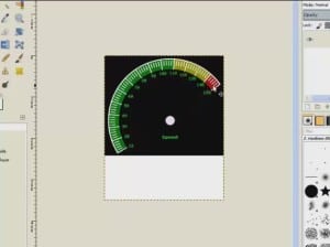
See our video tutorial called “Design a Needle for the Meter Define Command.”
There are no provisions for storing application files on the SD card, except for saving screenshots and using the screenshot command for customer product documentation. The SD card is used for system updates since this is much faster than using the RS-232 port. Otherwise, our modules are intended to be human interface devices only.
We recommend using the approach described in our In-System-Programming Application Note.
See the “xset” command in the Software Manual (find the manual for your module from the Touchscreen Display Modules menu, in the Documents tab) for information on adding touch characteristics to a button or hotspot.
When drawing a full-screen bitmap (.BMP) and using hotspots within it for control, the hotspots invoke macros. The macros redraw the screen. The colors being wrong is a side effect of how typical hotspots work. A standard hotspot defined by the “x” command specifies a touch-active area. When the area is touched, the screen is reverse imaged (foreground becomes background and vice versa) to provide visual feedback of the touch. When the button invokes a macro that redraws the screen, the screen is drawn while the button is pushed and the foreground/background colors are reversed. Then when the button is released, the hotspot is reversed even though the underlying image has changed. The solution is to use the “xs” command that does not change the screen when the defined hotspot is touched. The new screen will provide visual feedback, or the macro can do its reverse imaging.
The macros in the “macros_radio_button_ex.txt” file define a set of six buttons that act like radio buttons. Each button press calls an associated macro that sets the proper state for the button that was pressed and clears the state of the other buttons. The user would add application-specific commands to these macros.
Button text is limited to 19 characters for button numbers less than 118 and 49 characters for button numbers 118 and up (SLCD+ is always limited to 19 characters).
The SLCD board has an 80KB frame buffer which povides for 8-bit per-pixel color at 320 x 240 resolution. A constant color palette is used to support a consistent color image with multiple on-screen bitmaps. The palette maps the 8-bit pixel index to the 12-bit color value sent to the panel.
The palette provides 16 grayscales (including black and white) and six color values for red, green, and blue, or 6*6*6*16 = 231 colors (actually only 230 because of black redundancy).
In 24-bit RGB terms, the colors supported are as follows:
R, G, B = independently either 0x00, 0x33, 0x66, 0x99, 0xCC or 0xFF (six colors)
R=G=B = 0x00, 0x11, 0x22, …0xEE, 0xFF (16 grays).
A file ps8666.act is provided that contains the Adobe Photoshop palette corresponding to this color mapping.
Video
See 29 touch screen control panel interface designs using Reach modules in this 1:34 minute video.
Screen Shot Examples
Here are some still screenshots of touch screen control panel customer examples.
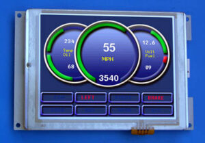
Chetco Digital uses 5.7″ QVGA touch screen control panels to create the display below. See several other screenshots. Chetco Digital makes an analog to digital instrumentation hub, enabling a touch screen gauge interface, remote switching, engine data logging, and SeaSmart.NET NMEA 2000 compatible wireless networking for marine, automotive, and industrial applications.
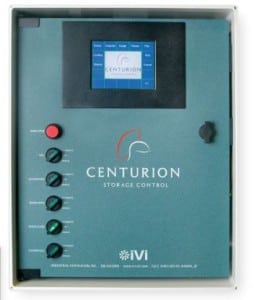
Industrial Ventialcaiton, Inc. makes Centurion, a stand-alone control unit that easily and precisely manages storage climates by controlling fans, evaporative coolers, heaters, refrigeration, humidification, Co2, and fresh air. It uses a Reach Technology 5.7″ display module.
Sciton uses an 8.4″ display module in JOULE, which offers an unprecedented array of laser and light wavelengths through its three distinct delivery modes: arm, fiber, and broadband light. As a result, JOULE allows practitioners the maximum versatility to provide the broadest range of aesthetic and surgical procedures available from a single platform.

Bitmaps are RLE compressed for storage. To see the effect of compression on a particular image, download the BMPload program and run it. Ignore the initial error (no SLCD attached) and add a bitmap. Then click on the bitmap name, and the information on the right-hand side will show the compressed size.
Note: If the bitmap is palletized using the SLCD palette, the 768 bytes of palette data does not need to be stored in the flash memory.
To display a changing number, use a monospace font and always write the same number of characters. So, if it is a 4-digit number, and the value is 1, send ” 1″ (three spaces and a 1) and if it is 123, send one space and the three numbers. The monospace font ensures that each number takes the same horizontal space, so they don’t shift left and right as they change. Finally, you may want to add a “wvr” command (find the manual for your display module in the Documents tab for your specific product) to ensure that the number changes while the display is not being refreshed on that part of the screen. Note that wvr does not work in portrait mode due to the way the LCD is built. See also our video tutorial called “Simple Output Formatting to Manage Fixed-Width Fields.”
Here are some suggestions to improve performance:
- Only send changed data: The host computer on boot can send all data. Afterward, the host computer should only send that data that has changed (compared with the last data sent).
- Reduce host computer data transmitting frequency: Reduce the rate of the data sent from the host computer to the SLCDx display controller to reduce the flicker that occurs when writing data.
- Avoid refreshing the entire screen: If you have a large bitmap, try to avoid re-displaying the bitmap since re-writing the bitmap can be relatively slow.
- Move Reach commands to macros: Commands executed within a macro are stored in the device memory, and these commands run faster than commands sent serially.
- Uncompressed images display quickest: If you are compressing images, remember that uncompressed versions are displayed faster. If the default is to compress all images, include the “.unc.” in the filename of large images that display more slowly.
The Flash memory has 25-year (!) data retention and 1,000,000 write and erase cycle durability.
Bitmaps can be compressed in our SLCD based products to save Flash memory space. The disadvantage is that compressed bitmaps display more slowly. To balance performance and Flash display storage, it is best to use the “Enable Bitmap Compression” checkbox in the BMPload application. For bitmaps that are large (for example cover the entire screen), or are re-drawn often, compression can be disabled by using inserting the string “.unc” into the file name, e.g. “01_MyBitmap.unc.bmp”. This tells the BMPload program not to compress this file’s image. Background bitmaps for slider objects and meter objects and sliding graphics (“xio” command) need to be uncompressed as well.
The SLCDx controllers can run either 8-bit color or high-color firmware (the original SLCD is 8-bit only, for high-color, use the SLCD+). In 8-bit color firmware, when a 24-bit “exact” palletized image is displayed, the bitmap routine maps the 24-bit color to the closest available in the fixed SLCD palette. In high-color firmware, the BMPload program converts 24-bit color bitmaps to 16-bit color (RGB565 format) before storing them on the controller board.
With Reach Technology products, you do not need to redesign your PCB, assuming it will be the “Host Computer,” provided it has a serial bus (USB, RS-232 UART, CMOS/TTL UART depending upon product).
Use a transparent bitmap. This feature is only available with high-color firmware versions; the “vers” command will show the version you are using.
To use transparency, create a 24-bit color bitmap with a fixed color for the transparent (non-displayed) pixels. Let’s say you used pure red. In 24-bit terms, this color is hex FF0000 (RRGGBB format). The high color firmware uses RGB565, that is, 5 bits of red, 6 of green, and 5 of blue. So it would be best if you converted the 24-bit color value to 16-bit. In this example, it would be hex F800. Then add the string “.trf800” to the name of the bitmap, and it becomes a transparent bitmap. (The transparency value has to be put in the filename because the .BMP format cannot specify a transparent color value). To get the 565RGB value corresponding to a 24-bit RRGGBB color, use the ‘S’ command to set the fg/bg color in RRGGBB format; the command will respond and show the RRGGBB values and their corresponding RGB565 values.
See the manual section “Working With Bitmaps” for more detail. You can download the manual by locating your module in the Touchscreen Display Module menu and then the Documents tab.
The BMPload program displays the full path and file name to load files in different directories. It makes the display hard to read, but it positively identifies the location of each bitmap file.
This is a feature of Windows, it tries to keep USB ports unique, so when you plug in a particular device, it holds the same COM port number it was first assigned. There is a way around this. Our board uses an FT232R chip, and the chip manufacturer has an application note to tell Windows to use the same COM port. See Application Note, Section 7.1, Ignore Hardware Serial Number.
In a nutshell, you have to edit the registry and add a key with a value of “01”:HKEY_LOCAL_MACHINE\SYSTEM\CurrentControlSet\Control\UsbFlags\IgnoreHWSerNum04036001
Please heed the application note warning about editing the Windows Registry.
There are two or three LEDs on the controller board, depending on the model. One LED is a “controller good indicator” that comes on when the controller firmware has powered up and is running. This LED shows the unit has power. The second is a “controller busy indicator” that lights up during command processing or upgrades/downloads. Some boards have a third LED, which indicates activity on the USB port.
To clear a power-on macro, use the BMPload program, check the “Set Power On Macro,” and set the Power On Macro to 0. This will turn the power-on macro feature off. It can also be done via the serial port using the command:
*PONMAC 0
The command:
*PONMAC 0 0
will also restore the copyright message usually suppressed when a power-on macro is assigned.
Similarly, check the “Set Splash Screen” and set Bitmap Number to 0, which will disable the splash screen. The splash screen and power-on macro are typically not set together.
The free Open Source program GIMP is helpful. See video tutorials for more information.
Although we do not have a canned graphics library, you can get bitmaps of buttons and other controls to use in your interface from iStockphoto. There you will find good quality graphics, for a low cost. Do a search on “buttons” to see a sample. Some other options: Free SVG or find other image galleries. You can use Inkscape to convert a .SVG to a .BMP. You might also consider using a tool like GIMP. See Reach Technology video tutorials for making graphic elements. You might also consider working with an interface design firm like GUIFX.
Currently, SLCD products only support BMP file formats. However, many image applications (Microsoft Paint, Adobe Photoshop, etc.) allow conversion from non-BMP to BMP file formats. Watch tutorial videos for more details.
We have no Programmable System On Chip silicon on our SLCD controller boards.
Thanks to one of our customers, there is a way to edit your SLCD macro files and have syntax highlighting. The TextPad shareware editor can do the custom highlighting. Download this ReachMacros.syn file and follow these instructions. You should now see macro highlighting in TextPad. Please note that Reach Technology is not responsible for supporting this file.
Spill resistance is a function of the case, not the display. The gaskets in our enclosed units provide an effective waterproof seal and dustproof seal, but only when mounted in a suitable enclosure. While our Enclosed Units currently do not have NEMA or IP ratings, we have several customers using these units in dusty and wet environments. Search for “enclosed” on this site for more information.
If there are problems with EMI emissions on the 5.7″ or 7″ modules, you can try using a ferrite core on the flat flex cable.
We have not done a full EMC/EMI report since modules are not finished products. Likewise, self CE certification has to be done on a finished product, and our modules are sub-assemblies. We have had many customers pass CE and FCC testing with varying enclosures. We do have an EMC “prescan” of the SLCD43 (currently shipping model, 40 pin 400 nit) with an FCC Class A limit line taken while the display was showing a “checkerboard” pattern, which is the worst case for display EMI. We use a spread spectrum oscillator for the display, which helps spread emissions. See the report.
To provide added ESD protection to the SLCD43 display modules, we use 3M 1170 conductive tape to connect the metal frame of the LCD panel to the digital ground (equals ESD or chassis ground) on the SLCD43 controller board. The controller board has grounded mounting holes that need a solid connection to chassis/Earth/ ESD ground. This approach provides approximately 4KV ESD protection. However, from a regulatory point of view, ESD testing has to be done with the display module in the customer’s enclosure with a system ground. If you are trying for high ESD immunity, the bezel “should” be metal or metalized plastic, although it may be OK with just plain plastic. Our suggestions are:
- If using a plastic bezel, add a metalization coating to the plastic bezel, and ensure good contact between it and the front panel.
- Use a flexible conductive gasket to ground the metal frame of the LCD panel to the front panel metal. Sold as EMI shields, they also work well for ESD. See example.
- Use a metal bezel. The SLCD43 can pass 16KV ESD testing without issues with a metal bezel.
We have tested the 5.7″ Standard Enclosed Unit. It successfully passed the EMC tests. For detailed information, please see the test report.
Maple Systems touch screens are highly feature-rich regarding speed and connectivity; hence, they’re more complicated to use (and more costly). If you don’t need 3D animations, the ability to play video or music, or Ethernet connectivity, you will find our SLCD solution more than adequate and much simpler to use. If you need some of those features, check out our G2 display modules. Since our SLCD interface to your system is a Command Line Interface implemented over a serial port, any UART microcontroller with enough speed and memory to handle your application will do just fine. If you want to discuss your application requirements and which of our products will best meet your needs, please contact our technical support team.
Note: If you do need 3D animations, video, or Ethernet, be sure to look at our G2/G3 modules, which use an industry-standard IDE (Qt Creator), programming language (QML), and operating system (Linux).
You would be better served using one of the following vendors to get an LCD controller with an analog VGA interface:
- Digital View: Look in the Products, LCD Controllers section.
- Spectrah Dynamics
To move QML code to the display module, follow the instructions below based on your user type.
Windows Users
Reach Technology has developed a Qt application called G2Link. It has a “Publish and Run” button that copies files to the display module, then restarts the QML Viewer. Visit G2Link to download the software and learn how to use this simple tool.
Linux Users
See Linux Deploy.
Network Connection
For information about connecting the module to your network, see Networking.
You need to use the UTF-8 format of the character. For conversion between Unicode and UTF-8, see http://www.utf8-chartable.de/. In your case, the bullet character 0xB7 is c2 b7, so the text command would be:
utf8 on
t “\xc2\xb7” 100 100
Here’s a handy online conversion utility: http://www.ltg.ed.ac.uk/~richard/utf-8.cgi?input=b7&mode=hex
There are probably formulas to work these out in your application as well. Here is more detail than you might want: http://en.wikipedia.org/wiki/UTF-8
A font file such as a .TTF that contains details about how to render a font in different sizes is subject to licensing. However, when fonts are rendered in a particular size and attribute (bold, italic, etc.), such as in our .SIF files, it is no longer copyrightable and needs no license to be used.
Here is an example of printing the special characters “, \, and % in ‘C’ strings using our API.
void demoSpecialChars(void)
{
char buf[120];
sprintf(buf,”f 24″); // set font size 24
sendToSerialPort(buf);
sprintf(buf,”s 0 1″); // set black on white
sendToSerialPort(buf);
sprintf(buf,”z”); // clear screen
sendToSerialPort(buf);
sprintf(buf,”t \”%s\”\r”,”Backslash: \\\\“); // backslash in string
sendToSerialPort(buf);
sendToSerialPort(“t \”\n\”\r”); // newline
// backslash as character
sprintf(buf,”t \”%s%c%c\”\r”,”Backslash: “,’\\’,’\\’);
sendToSerialPort(buf);
sendToSerialPort(“t \”\n\”\r”); // newline
sprintf(buf,”t \”%s\”\r”,”Percent: %”); // Percent
sendToSerialPort(buf);
sendToSerialPort(“t \”\n\”\r”); // newline
sprintf(buf,”t \”Percent: %%\”\r”); // Percent
sendToSerialPort(buf);
sendToSerialPort(“t \”\n\”\r”); // newline
// Quote (need 2 to get one for SLCD, and one more to allow ” in string)
sprintf(buf,”t \”%s\”\r”,”Quote: \\\“”);
sendToSerialPort(buf);
sendToSerialPort(“t \”\n\”\r”); // newline
// Quote as character
sprintf(buf,”t \”%s%c%c\”\r”,”Quote: “,’\\’,’“‘);
sendToSerialPort(buf);
sendToSerialPort(“t \”\n\”\r”); // newline
}
We have font files on our web page that should work for you. Look in the Arial Unicode Fonts Folder for the Unicode fonts in the size you need. The Cyrillic fonts are in the ranges 0x0400-0x04FF and 0x0500-0x05FF. Another useful font site lets you see the characters and display codes for many different fonts.
We need the Windows font name for fonts, size in pixels or points, and Unicode range required. Per Wikipedia, ISCII uses an 8-bit code, an extension of the 7-bit ASCII code containing the basic alphabet necessary for the ten Indian scripts originating from the Brahmi script. There are 15 officially recognized languages in India. Apart from Perso-Arabic scripts, the other ten scripts used for Indian languages have evolved from ancient Brahmi and have a similar phonetic structure, making a standard character set possible. The ISCII code table is a superset of all the characters required in the Brahmi-based Indian scripts. For convenience, we use the alphabet of the official script Devanagari. We can provide downloadable fonts accessed as 8-bit characters if you can provide a font with ISCII characters.
See Fonts for Embedded Touch Screen Development for a comprehensive explanation of working with fonts.
Use Photoshop or the open-source equivalent GIMP to design a user interface screen on a PC. It can be hard to match the embedded fonts on the SLCD family of controllers with Windows fonts. If you need an exact match, you must do two things:
- Set image scaling in the Windows design program to 96 dpi (establish the size/scale) and;
- Use a Reach Technology generated downloadable font of the same font name and point size. Find fonts.
If you need fonts not shown, please get in touch with the technical support team and specify the Windows font name, the size in points, and the character set (either ISO 8859-1 or a Unicode subset). See the Fonts for Embedded Touch Screen Development for a comprehensive explanation of working with fonts.
Downloadable fonts are rendered from True Type or Open Type Windows fonts and then stored in .SIF files. One file for each font type, size, attribute (i.e., italic, bold), and character subset included. Please specify if you want a standard character set (extended ASCII like ISO 8859-X). ISO sets defined. If we do not offer the characters you need, please don’t hesitate to contact our technical support team and specify the Unicode subset you need.
We support UTF-8 encoding. Find UTF-8 for a given Unicode. For Unicode, the subset size determines the size of the .SIF font. The complete Unicode set of a font like SimSun at 16 pixels high (not 16-point) is 946KB and has over 20,000 characters. See Fonts for Embedded Touch Screen Development for a comprehensive explanation of working with fonts.
We have several customers running LabVIEW applications that use our display modules in their products. LabVIEW communicates with our modules using ASCII strings to receive commands and send replies. We do not offer LabVIEW drivers for our display modules, but National Instruments has a driver that works with some of our modules. National Instruments wrote the LabVIEW driver, so you need to contact them to get more information or answers to questions. Some of the bitmaps in the LabVIEW application are incorrect. Bitmaps 15 thru 18 are in the wrong format, and you will need to convert them to 24-bit for use on some Reach Technology modules.
The (4-40) – it is a tight fit.
You may hear our enclosed units referred to as, GOITs which stands for Graphics Operator Interface Terminal.
The “Vertical Mount” display module has mounting tabs on the long sides of the display module, with the tabs aligned vertically when the module is in landscape orientation.
The “Horizontal Mount” display module has these tabs on the short sides, with the tabs aligned horizontally when the module is in landscape orientation. The two options allow customers to fit a module into either a narrow or short space.
In both cases, the default orientation is landscape, with the long sides horizontal, but the modules may also be used in portrait mode with an alternate firmware load.
Compressing bitmaps in our SLCD products allows you to save Flash memory space. The disadvantage is that compressed bitmaps display more slowly. To balance performance and Flash display storage, it is best to use the “Enable Bitmap Compression” checkbox in the BMPload application. For bitmaps that are large (i.e., cover the entire screen), or are re-drawn often, disable compression by inserting the string “.unc” into the file name (e.g. “01_MyBitmap.unc.bmp”). This string tells the BMPload program not to compress this image. Background bitmaps for slider objects and meter objects and sliding graphics (“xio” command) need to be uncompressed. Using the strategy above should keep your application visually responsive while conserving Flash memory for future additional bitmaps.
Detection time depends on user-adjustable touch parameters. Factory settings recognize touches in around 20ms. The corresponding serial response sends immediately if no commands are being executed. However, there is no guarantee since the screen could be performing some command when the unit is touched. The evaluation kit unit has a very responsive keyboard demo. However, the ultimate response time depends on how the unit is used.
If you are an engineer or have any programming experience, you can get one of our SLCD touchscreen modules up and running. See the example code in the Software Reference Manual. ![]()
You might also benefit from watching this touch screen programming video and other tutorial videos on our site.
We do have partner consultants who have worked with our products. Customers have also had good luck using Guifx for graphics development.
No, we only support serial data transfer. We do not support parallel data transfer.
UART is the only serial bus we support: RS-232, TTL/CMOS, and on some modules, USB. We also support an RS-485 like addressed protocol over the UART.
We do not support Modbus RTU Protocol (software).
Our display controllers do not directly support this J1939 vehicle communications standard. If you found a host computer (ex., microprocessor board) that does use J1939, it may be possible to use the data from this protocol with our display controllers. The host computer needs either RS-232, TTL, or USB (depending on the module) to receive the data using our command set.
SLCD controller boards use PicoBlade connectors. They are made by Molex and are miniature (1.25mm pitch) which makes them hard to make by hand. International Component Technology can make these cables for you to use to connect to your microcontroller board.
Embedded Touchscreens Made Easy:
Up in Days, Smoothly to Production. Get started with a Development Kit.
Reach Technology is now a part of Novanta.
Sales and Engineering
545 First Street
Lake Oswego, OR 97034
503-675-6464
sales@reachtech.com
techsupport@reachtech.com
Manufacturing
4600 Campus Place
Mukilteo, WA 98275
service@reachtech.com
Please send payments to:
Novanta Corporation
PO Box 15905
Chicago, IL 60693
accounts.receivable
@novanta.com